Camera
The most important flight instrument is the “Mark 1 Eyeball,” or just moving your head without having to turn your aircraft. Open up the Settings – Controls, look under the “Actions” control selector, and map “Horizontal Camera Rotation,” “Vertical Camera Rotation,” and “Reset Camera Location” to convenient functions on your controller. If you are short on axes to assign you can map these as buttons; a D-pad or joystick hat switch is a good choice.
You can also move the camera through several pre-set positions around your aircraft. The camera defaults to above and slightly behind, but can also move to: Dorsal (directly above); Rear Cockpit; Front Cockpit; No Cockpit; Right Wing; Left Wing; and Rear View.
There are controls for “Next Camera Position” and “Previous Camera Position” but since the camera positions cycle around, the second control is a convenience, not a requirement.
Heads-Up Display (HUD) – Vertical Flight
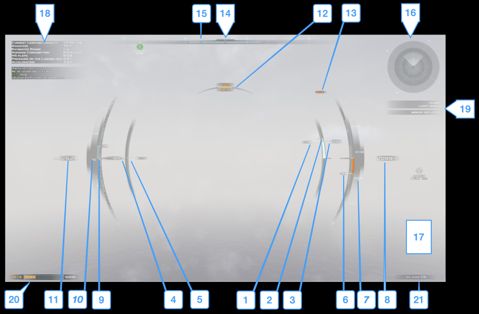
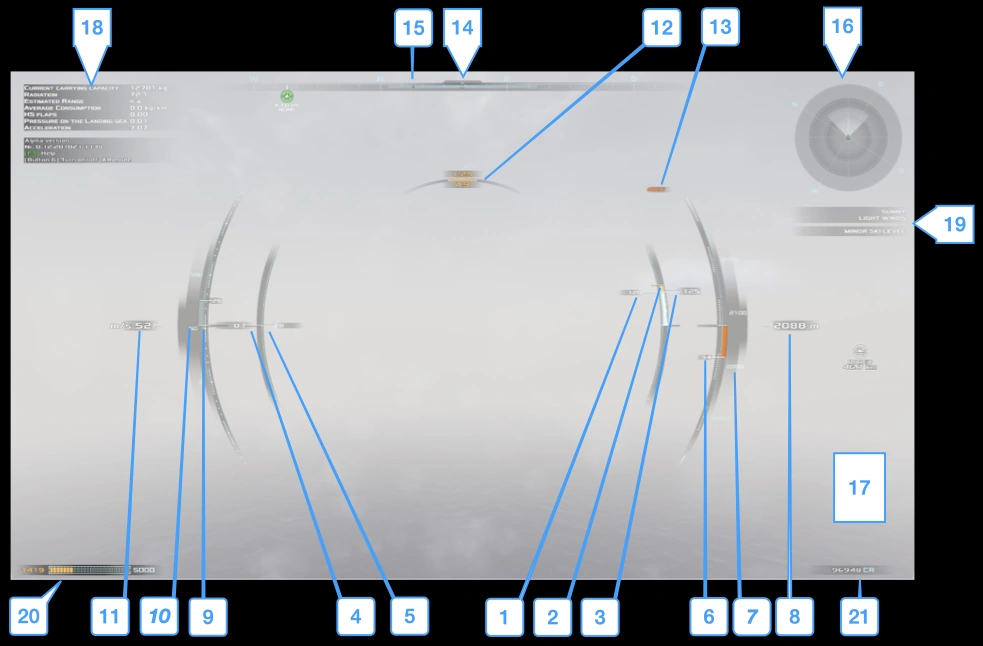
| 1. Engine Thrust – Actual thrust generated by the engines. This may be less than the Throttle Position due to engine damage. 2. Thrust/Weight Equivalence – Thrust needed to offset the weight of the aircraft. Matching Engine Thrust to this indicator enables a stationary hover (when the engine nozzles are pointed straight down and the aircraft is straight and level.) 3. Throttle Position and Overthrust Indicator – Current throttle setting. Changes color from green, to yellow, to red, to indicate the requested throttle setting may cause engine damage over time. 4. Thrust Vector Position – The position of the engines relative to the aircraft’s vertical axis. 0 indicates the engine nozzles are pointed straight down. Positive/negative values indicate the engines are angled to allow forward/reverse translation. 5. Vectored Thrust – The amount of Engine Thrust which is applied to forward/reverse airspeed (see Powered Lift) 6. Vertical Speed Indicator – The rate of aircraft climb/descent, in meters/second. 7. Altitude Tape with Ceiling/AGL Indicators – Current altitude in a scrolling “tape” which gives a sense of vertical speed. A “ceiling” indicator appears as the aircraft nears the SKI Altitude. As the aircraft nears the ground, an orange indicator appears showing the current Altitude Above Ground Level (AGL). 8. Altitude (MSL) – Meters above Mean Sea Level (MSL). 9. Accelerometer – SPEC: The rate at which airspeed is increasing/decreasing. 0 indicates constant speed. | 10. Airspeed Tape with Max/Min Airspeed Indicators – Similar to the Altitude Tape, but for airspeed. As the aircraft approaches maximum safe speed, or stall speed, indicators appear at the top/bottom of the tape. 11. Airspeed – Exact airspeed in meters/second. 12. Aircraft Endurance Indicator – Top number is current flight time remaining at current Engine Thrust, bottom indicates current distance remaining. 13. SKI Altitude – The altitude at which SKI will start to affect the aircraft. 14. Heading Indicator – Electronic compass showing which way the nose of the aircraft is pointed. 15. Flight Path Indicator – The aircraft’s flight path may not match its heading; this indicator shows the aircraft’s actual flight path. 16. Mini-Map – Key elements from the map, see “HUD MiniMap” below. 17. Landing Camera – The Landing Camera appears here, see below for details. 18. Aircraft Conditions – Various aircraft conditions; “Carrying Capacity” is worth noting. 19. Weather Conditions – Current weather and SKI warnings. 20. Fuel/Charge Indicator – Fuel/Charge capacity and amount remaining. 21. Credit Balance – Your funds. |
HUD MiniMap
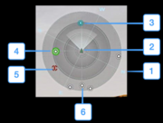
- Cardinal Compass Directions
- Your Aircraft
- Waypoint – The next waypoint in your route. See Interface – Map and Trade for information on setting waypoints and plotting routes.
- Targeted Base – A base that you have set as your target (destination).
- Hazard – An environmental hazard like a volcano or geyser.
- Base (not Targeted) – Other bases nearby.
Landing Camera
The Landing Camera (“Landing Cam”) appears any time your aircraft is less than 100m altitude above ground level (AGL).
The Landing Cam is a little odd; currently it behaves as if it were mounted on a very tall pole above your aircraft. It looks down onto your aircraft, but more frustratingly, it also pitches and rolls with your aircraft’s pitch and roll. This means you could be directly above your landing spot, but if the aircraft is tilted it will look as if you were farther away from it. Hopefully this behavior will change in the future.
General advice is only trust the Landing Cam when you’re straight and level; and only look at it in short glances. You’re flying the aircraft, not the Landing Cam.
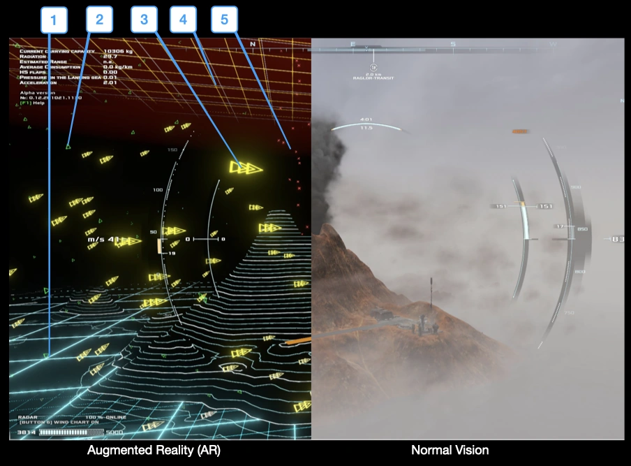
Augmented Reality
Augmented Reality is a HUD view which allows the pilot to see in the dark/through fog, and also highlights wind and atmospheric hazards. A split screen view — AR and normal vision — is below:
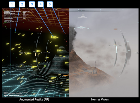
| Water/Sea Level AltitudeWind (low speed)Wind (moderate speed)SKI AltitudeAtmospheric Hazard | Split screen view of AR and out the cockpit with key to symbology |
HUD – Horizontal Flight
TODO: Is an annotated image of the HUD for horizontal flight really needed?
When the aircraft transitions from vertical flight to horizontal flight, the HUD takes a few changes:
- Vectored Thrust gets set to +100% of Engine Thrust – The engines are in their full-forward configuration, and the aircraft now flies like an airplane.
- Pitch Ladder – A “ladder” appears in the center of the HUD showing the aircraft’s current pitch, in degrees.
- Bank Indicator – Above the Aircraft Endurance Indicator, a curved indicator appears to show the aircraft’s current bank angle, in degrees.
- Trim Tabs – To either side of the HUD, triangular arrows appear to show the current trim tab setting.